Description
Description
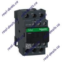
| RANGE OF PRODUCT | TeSys Deca |
|---|---|
| PRODUCT OR COMPONENT TYPE | Contactor |
| DEVICE SHORT NAME | LC1D |
| CONTACTOR APPLICATION | Motor control Resistive load |
| UTILISATION CATEGORY | AC-3 AC-1 AC-3e |
| POLES DESCRIPTION | 3P |
| [UE] RATED OPERATIONAL VOLTAGE | Power circuit: <= 690 V AC 25…400 Hz Power circuit: <= 300 V DC |
| [IE] RATED OPERATIONAL CURRENT | 25 A (at <60 °C) at <= 440 V AC AC-3 for power circuit 40 A (at <60 °C) at <= 440 V AC AC-1 for power circuit 25 A (at <60 °C) at <= 440 V AC AC-3e for power circuit |
| [UC] CONTROL CIRCUIT VOLTAGE | 240 V AC 50/60 Hz |
| MOTOR POWER KW | 5.5 kW at 220…230 V AC 50/60 Hz (AC-3) 11 kW at 380…400 V AC 50/60 Hz (AC-3) 11 kW at 415…440 V AC 50/60 Hz (AC-3) 15 kW at 500 V AC 50/60 Hz (AC-3) 15 kW at 660…690 V AC 50/60 Hz (AC-3) 5.5 kW at 400 V AC 50/60 Hz (AC-4) 5.5 kW at 220…230 V AC 50/60 Hz (AC-3e) 11 kW at 380…400 V AC 50/60 Hz (AC-3e) 11 kW at 415…440 V AC 50/60 Hz (AC-3e) 15 kW at 500 V AC 50/60 Hz (AC-3e) 15 kW at 660…690 V AC 50/60 Hz (AC-3e) |
|---|---|
| MOTOR POWER HP | 3 hp at 230/240 V AC 50/60 Hz for 1 phase motors 2 hp at 115 V AC 50/60 Hz for 1 phase motors 7.5 hp at 230/240 V AC 50/60 Hz for 3 phases motors 15 hp at 460/480 V AC 50/60 Hz for 3 phases motors 20 hp at 575/600 V AC 50/60 Hz for 3 phases motors 7.5 hp at 200/208 V AC 50/60 Hz for 3 phases motors |
| COMPATIBILITY CODE | LC1D |
| POLE CONTACT COMPOSITION | 3 NO |
| CONTACT COMPATIBILITY | M2 |
| PROTECTIVE COVER | With |
| [ITH] CONVENTIONAL FREE AIR THERMAL CURRENT | 10 A (at 60 °C) for signalling circuit 40 A (at 60 °C) for power circuit |
| IRMS RATED MAKING CAPACITY | 140 A AC for signalling circuit conforming to IEC 60947-5-1 250 A DC for signalling circuit conforming to IEC 60947-5-1 450 A at 440 V for power circuit conforming to IEC 60947 |
| RATED BREAKING CAPACITY | 450 A at 440 V for power circuit conforming to IEC 60947 |
| [ICW] RATED SHORT-TIME WITHSTAND CURRENT | 240 A 40 °C – 10 s for power circuit 380 A 40 °C – 1 s for power circuit 50 A 40 °C – 10 min for power circuit 120 A 40 °C – 1 min for power circuit 100 A – 1 s for signalling circuit 120 A – 500 ms for signalling circuit 140 A – 100 ms for signalling circuit |
| ASSOCIATED FUSE RATING | 10 A gG for signalling circuit conforming to IEC 60947-5-1 63 A gG at <= 690 V coordination type 1 for power circuit 40 A gG at <= 690 V coordination type 2 for power circuit |
| AVERAGE IMPEDANCE | 2 mOhm – Ith 40 A 50 Hz for power circuit |
| POWER DISSIPATION PER POLE | 3.2 W AC-1 1.25 W AC-3 1.25 W AC-3e |
| [UI] RATED INSULATION VOLTAGE | Power circuit: 690 V conforming to IEC 60947-4-1 Power circuit: 600 V CSA certified Power circuit: 600 V UL certified Signalling circuit: 690 V conforming to IEC 60947-1 Signalling circuit: 600 V CSA certified Signalling circuit: 600 V UL certified |
| OVERVOLTAGE CATEGORY | III |
| POLLUTION DEGREE | 3 |
| [UIMP] RATED IMPULSE WITHSTAND VOLTAGE | 6 kV conforming to IEC 60947 |
| SAFETY RELIABILITY LEVEL | B10d = 1369863 cycles contactor with nominal load conforming to EN/ISO 13849-1 B10d = 20000000 cycles contactor with mechanical load conforming to EN/ISO 13849-1 |
| MECHANICAL DURABILITY | 15 Mcycles |
| ELECTRICAL DURABILITY | 1.65 Mcycles 25 A AC-3 at Ue <= 440 V 1.4 Mcycles 40 A AC-1 at Ue <= 440 V 1.65 Mcycles 25 A AC-3e at Ue <= 440 V |
| CONTROL CIRCUIT TYPE | AC at 50/60 Hz |
| COIL TECHNOLOGY | Without built-in suppressor module |
| CONTROL CIRCUIT VOLTAGE LIMITS | 0.3…0.6 Uc (-40…70 °C):drop-out AC 50/60 Hz 0.8…1.1 Uc (-40…60 °C):operational AC 50 Hz 0.85…1.1 Uc (-40…60 °C):operational AC 60 Hz 1…1.1 Uc (60…70 °C):operational AC 50/60 Hz |
| INRUSH POWER IN VA | 70 VA 60 Hz cos phi 0.75 (at 20 °C) 70 VA 50 Hz cos phi 0.75 (at 20 °C) |
| HOLD-IN POWER CONSUMPTION IN VA | 7.5 VA 60 Hz cos phi 0.3 (at 20 °C) 7 VA 50 Hz cos phi 0.3 (at 20 °C) |
| HEAT DISSIPATION | 2…3 W at 50/60 Hz |
| OPERATING TIME | 12…22 ms closing 4…19 ms opening |
| MAXIMUM OPERATING RATE | 3600 cyc/h 60 °C |
| CONNECTIONS – TERMINALS | Control circuit: screw clamp terminals 1 1…4 mm² – cable stiffness: flexible without cable end Control circuit: screw clamp terminals 2 1…4 mm² – cable stiffness: flexible without cable end Control circuit: screw clamp terminals 1 1…4 mm² – cable stiffness: flexible with cable end Control circuit: screw clamp terminals 2 1…2.5 mm² – cable stiffness: flexible with cable end Control circuit: screw clamp terminals 1 1…4 mm² – cable stiffness: solid without cable end Control circuit: screw clamp terminals 2 1…4 mm² – cable stiffness: solid without cable end Power circuit: screw clamp terminals 1 2.5…10 mm² – cable stiffness: flexible without cable end Power circuit: screw clamp terminals 2 2.5…10 mm² – cable stiffness: flexible without cable end Power circuit: screw clamp terminals 1 1…10 mm² – cable stiffness: flexible with cable end Power circuit: screw clamp terminals 2 1.5…6 mm² – cable stiffness: flexible with cable end Power circuit: screw clamp terminals 1 1.5…10 mm² – cable stiffness: solid without cable end Power circuit: screw clamp terminals 2 2.5…10 mm² – cable stiffness: solid without cable end |
| TIGHTENING TORQUE | Control circuit: 1.7 N.m – on screw clamp terminals – with screwdriver flat Ø 6 mm Control circuit: 1.7 N.m – on screw clamp terminals – with screwdriver Philips No 2 Power circuit: 2.5 N.m – on screw clamp terminals – with screwdriver flat Ø 6 mm Power circuit: 2.5 N.m – on screw clamp terminals – with screwdriver Philips No 2 Control circuit: 1.7 N.m – on screw clamp terminals – with screwdriver pozidriv No 2 Power circuit: 2.5 N.m – on screw clamp terminals – with screwdriver pozidriv No 2 |
| AUXILIARY CONTACT COMPOSITION | 1 NO + 1 NC |
| AUXILIARY CONTACTS TYPE | Type mechanically linked 1 NO + 1 NC conforming to IEC 60947-5-1 type mirror contact 1 NC conforming to IEC 60947-4-1 |
| SIGNALLING CIRCUIT FREQUENCY | 25…400 Hz |
| MINIMUM SWITCHING VOLTAGE | 17 V for signalling circuit |
| MINIMUM SWITCHING CURRENT | 5 mA for signalling circuit |
| INSULATION RESISTANCE | > 10 MOhm for signalling circuit |
| NON-OVERLAP TIME | 1.5 ms on de-energisation between NC and NO contact 1.5 ms on energisation between NC and NO contact |
| MOUNTING SUPPORT | Rail Plate |
| STANDARDS | CSA C22.2 No 14 EN 60947-4-1 EN 60947-5-1 IEC 60947-4-1 IEC 60947-5-1 UL 508 IEC 60335-1 |
|---|---|
| PRODUCT CERTIFICATIONS | RINA CSA BV UL CCC LROS (Lloyds register of shipping) DNV GOST GL UKCA |
| IP DEGREE OF PROTECTION | IP20 front face conforming to IEC 60529 |
| PROTECTIVE TREATMENT | TH conforming to IEC 60068-2-30 |
| CLIMATIC WITHSTAND | Conforming to IACS E10 exposure to damp heat conforming to IEC 60947-1 Annex Q category D exposure to damp heat |
| PERMISSIBLE AMBIENT AIR TEMPERATURE AROUND THE DEVICE | -40…60 °C 60…70 °C with derating |
| OPERATING ALTITUDE | 0…3000 m |
| FIRE RESISTANCE | 850 °C conforming to IEC 60695-2-1 |
| FLAME RETARDANCE | V1 conforming to UL 94 |
| MECHANICAL ROBUSTNESS | Vibrations contactor open (2 Gn, 5…300 Hz) Vibrations contactor closed (4 Gn, 5…300 Hz) Shocks contactor closed (15 Gn for 11 ms) Shocks contactor open (8 Gn for 11 ms) |
| HEIGHT | 85 mm |
| WIDTH | 45 mm |
| DEPTH | 92 mm |
| NET WEIGHT | 0.37 kg |
| UNIT TYPE OF PACKAGE 1 | PCE |
|---|---|
| NUMBER OF UNITS IN PACKAGE 1 | 1 |
| PACKAGE 1 HEIGHT | 5.0 cm |
| PACKAGE 1 WIDTH | 9.2 cm |
| PACKAGE 1 LENGTH | 11.2 cm |
| PACKAGE 1 WEIGHT | 414.0 g |
| UNIT TYPE OF PACKAGE 2 | S02 |
| NUMBER OF UNITS IN PACKAGE 2 | 20 |
| PACKAGE 2 HEIGHT | 15.0 cm |
| PACKAGE 2 WIDTH | 30.0 cm |
| PACKAGE 2 LENGTH | 40.0 cm |
| PACKAGE 2 WEIGHT | 8.715 kg |
| UNIT TYPE OF PACKAGE 3 | P06 |
| NUMBER OF UNITS IN PACKAGE 3 | 320 |
| PACKAGE 3 HEIGHT | 75.0 cm |
| PACKAGE 3 WIDTH | 80.0 cm |
| PACKAGE 3 LENGTH | 60.0 cm |
| PACKAGE 3 WEIGHT | 147.94 kg |


