Description
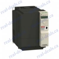
| Model: | ATV32HU75N4 |
| range of product |
Altivar 32
|
|
|---|---|---|
| product or component type |
Variable speed drive
|
|
| product destination |
Asynchronous motors
Synchronous motors |
|
| product specific application |
Complex machines
|
|
| function available |
–
|
|
| assembly style |
With heat sink
|
|
| component name |
ATV32
|
|
| EMC filter |
Class C2 EMC filter integrated
|
|
| network number of phases |
3 phases
|
|
| [Us] rated supply voltage |
380…500 V – 15…10 %
|
|
| supply voltage limits |
323…550 V
|
|
| supply frequency |
50…60 Hz – 5…5 %
|
|
| network frequency |
47.5…63 Hz
|
|
| motor power kW |
7.5 kW at 380…480 V
|
|
| motor power hp |
10 hp at 380…480 V
|
| line current |
18.7 A for 500 V 3 phases 7.5 kW / 10 hp
26.5 A for 380 V 3 phases 7.5 kW / 10 hp |
|
|---|---|---|
| apparent power |
22.9 kVA at 500 V 3 phases 7.5 kW / 15 hp
|
|
| prospective line Isc |
22 kA for 3 phases
|
|
| nominal output current |
17 A at 4 kHz 500 V 7.5 kW / 10 hp
|
|
| maximum transient current |
25.5 A for 60 s 7.5 kW / 10 hp
|
|
| Output frequency |
0.0005…0.599 kHz
|
|
| nominal switching frequency |
4 kHz
|
|
| switching frequency |
2…16 kHz adjustable
|
|
| speed range |
1…100 for asynchronous motor in open-loop mode
|
|
| speed accuracy |
+/- 10 % of nominal slip 0.2 Tn to Tn
|
|
| torque accuracy |
+/- 15 %
|
|
| transient overtorque |
170…200 %
|
|
| braking torque |
<= 170 % with braking resistor
|
|
| asynchronous motor control profile |
Flux vector control without sensor, standard
Voltage/frequency ratio, 2 points Flux vector control without sensor – Energy Saving, NoLoad law Voltage/frequency ratio, 5 points Voltage/frequency ratio – Energy Saving, quadratic U/f |
|
| synchronous motor control profile |
Vector control without sensor
|
|
| regulation loop |
Adjustable PID regulator
|
|
| motor slip compensation |
Not available in voltage/frequency ratio (2 or 5 points)
Adjustable 0…300 % Automatic whatever the load |
|
| local signalling |
1 LED red for drive voltage
1 LED green for CANopen run 1 LED red for CANopen error 1 LED red for drive fault |
|
| output voltage |
<= power supply voltage
|
|
| noise level |
43 dB conforming to 86/188/EEC
|
|
| insulation |
Electrical between power and control
|
|
| electrical connection |
Screw terminal, clamping capacity: 0.5…1.5 mm², AWG 18…AWG 14 (control)
Removable screw terminals, clamping capacity: 2.5…16 mm², AWG 12…AWG 6 (motor/braking resistor) Screw terminal, clamping capacity: 6…16 mm², AWG 8…AWG 6 (power supply) |
|
| tightening torque |
0.5 N.m, 4.4 lb/ft (control)
1.2 N.m, 10.6 lb/ft (motor/braking resistor) 1.2 N.m, 10.6 lb/ft (power supply) |
|
| supply |
Internal supply for reference potentiometer (1 to 10 kOhm): 10.5 V DC +/- 5 %, <10 mA, protection type: overload and short-circuit protection
|
|
| analogue input number |
3
|
|
| analogue input type |
AI1 voltage: 0…10 V DC, impedance: 30000 Ohm, resolution 10 bits
AI2 bipolar differential voltage: +/- 10 V DC, impedance: 30000 Ohm, resolution 10 bits AI3 current: 0…20 mA (or 4-20 mA, x-20 mA, 20-x mA or other patterns by configuration), impedance: 250 Ohm, resolution 10 bits |
|
| sampling duration |
2 ms (AI1, AI2, AI3) – analog input(s)
2 ms (AO1) – analog input(s) |
|
| response time |
LI1…LI6 8 ms, tolerance +/- 0.7 ms for logic output(s)
R1A, R1B, R1C 2 ms for relay output(s) R2A, R2C 2 ms for relay output(s) |
|
| accuracy |
+/- 0.2 % (AI1, AI2, AI3) for a temperature of -10…60 °C
+/- 0.5 % (AI1, AI2, AI3) for a temperature of 25 °C +/- 1 % (AO1) for a temperature of 25 °C +/- 2 % (AO1) for a temperature of -10…60 °C |
|
| linearity error |
+/- 0.2…0.5 % of maximum value (AI1, AI2, AI3)
+/- 0.3 % (AO1) |
|
| analogue output number |
1
|
|
| analogue output type |
AO1 software-configurable current 0…20 mA, impedance: 800 Ohm, resolution 10 bits
AO1 software-configurable voltage 0…10 V, impedance: 470 Ohm, resolution 10 bits |
|
| discrete output number |
3
|
|
| discrete output type |
Configurable relay logic: (R1A, R1B, R1C) NO/NC – 100000 cycles
Configurable relay logic: (R2A, R2B) NO – 100000 cycles Logic: (LO) |
|
| minimum switching current |
5 mA at 24 V DC for configurable relay logic
|
|
| maximum switching current |
R1: 3 A at 250 V AC resistive load, cos phi = 1
R1: 4 A at 30 V DC resistive load, cos phi = 1 R1, R2: 2 A at 250 V AC inductive load, cos phi = 0.4 R1, R2: 2 A at 30 V DC inductive load, cos phi = 0.4 R2: 5 A at 250 V AC resistive load, cos phi = 1 R2: 5 A at 30 V DC resistive load, cos phi = 1 |
|
| discrete input number |
7
|
|
| discrete input type |
Programmable (sink/source) (LI1…LI4)24…30 V DC, with level 1 PLC
Programmable as pulse input 20 kpps (LI5)24…30 V DC, with level 1 PLC Switch-configurable PTC probe (LI6)24…30 V DC Safe torque off (STO)24…30 V DC – 1500 Ohm |
|
| discrete input logic |
Negative logic (sink) (LI1…LI6), > 19 V (state 0), < 13 V (state 1)
Positive logic (source) (LI1…LI6), < 5 V (state 0), > 11 V (state 1) |
|
| acceleration and deceleration ramps |
Deceleration ramp automatic stop DC injection
S Linear Ramp switching U CUS Deceleration ramp adaptation |
|
| braking to standstill |
By DC injection
|
|
| protection type |
Input phase breaks: drive
Overcurrent between output phases and earth: drive Overheating protection: drive Short-circuit between motor phases: drive Thermal protection: drive |
|
| communication port protocol |
CANopen
Modbus |
|
| connector type |
1 RJ45 (on front face) for Modbus/CANopen
|
|
| physical interface |
2-wire RS 485 for Modbus
|
|
| transmission frame |
RTU for Modbus
|
|
| type of polarization |
No impedance for Modbus
|
|
| number of addresses |
1…127 for CANopen
1…247 for Modbus |
|
| method of access |
Slave CANopen
|
|
| electromagnetic compatibility |
1.2/50 µs – 8/20 µs surge immunity test, level 3 conforming to IEC 61000-4-5
Conducted radio-frequency immunity test, level 3 conforming to IEC 61000-4-6 Electrical fast transient/burst immunity test, level 4 conforming to IEC 61000-4-4 Electrostatic discharge immunity test, level 3 conforming to IEC 61000-4-2 Radiated radio-frequency electromagnetic field immunity test, level 3 conforming to IEC 61000-4-3 Voltage dips and interruptions immunity test conforming to IEC 61000-4-11 |
|
| width |
150 mm
|
|
| height |
308 mm
|
|
| depth |
232 mm
|
|
| net weight |
7.5 kg
|
|
| option card |
Communication card for CANopen daisy chain
Communication card for CANopen open style Communication card for DeviceNet Communication card for Ethernet/IP Communication card for Profibus DP V1 |
|
| functionality |
Mid
|
|
| specific application |
Other applications
|
| standards |
EN 61800-3 environments 2 category C2
EN/IEC 61800-3 EN/IEC 61800-5-1 EN 61800-3 environments 1 category C2 EN 55011 class A group 1 |
|
|---|---|---|
| product certifications |
NOM 117
GOST C-Tick UL CSA |
|
| marking |
CE
|
|
| pollution degree |
2 conforming to EN/IEC 61800-5-1
|
|
| IP degree of protection |
IP20 conforming to EN/IEC 61800-5-1
|
|
| vibration resistance |
1 gn (f = 13…200 Hz) conforming to EN/IEC 60068-2-6
1.5 mm peak to peak (f = 3…13 Hz) conforming to EN/IEC 60068-2-6 |
|
| shock resistance |
15 gn for 11 ms conforming to EN/IEC 60068-2-27
|
|
| relative humidity |
5…95 % without condensation conforming to IEC 60068-2-3
5…95 % without dripping water conforming to IEC 60068-2-3 |
|
| ambient air temperature for operation |
-10…50 °C without derating
50…60 °C with derating factor |
|
| ambient air temperature for storage |
-25…70 °C
|
|
| operating altitude |
<= 1000 m without derating
1000…3000 m with current derating 1 % per 100 m |
|
| operating position |
Vertical +/- 10 degree
|
| Package 1 Weight |
5.604 kg
|
|
|---|---|---|
| Package 1 Height |
2.050 dm
|
|
| Package 1 width |
2.700 dm
|
|
| Package 1 Length |
3.300 dm
|
| Warranty |
18 months
|
|---|


